Rockets that can only fly with a single size motor are pretty boring, so I would like to have greater power choices for this design. I therefore hope to at least get this rocket over 100 feet with a 1/2A motor - the smallest I will bother to use. If I can construct this light enough, it should reach 335 feet on the A3-4 motor, 325 feet on the A10-3 motor, and if those go well, I could reach 118 feet on the 1/2A3-4 motor. Of course those are all computer simulation numbers, I'll have to adjust the projected performance based on the actual weights of the constructed parts, which usually ends up a bit heavier, especially with paint and glue added. I'll consider this a performance success if I can reach 100 feet on the 1/2A motor.


Here is a nosecone (a different one actually) being shaped with a sanding block while turning in a drill press. This is a great method for shaping precisely rounded nosecones, but you must make sure not to press too hard or the dowel will break. Also, hold the sandpaper very firmly or it may be out of round, and hold it on the side of the cone that is turing away from you, in case it grabs and throws the sandpaper.


Next I started making the motor mount and then inserted it into a 18" length of tube for the main body. I cut another 3-1/2" section for the payload tube and used another coupler to join the two. The coupler will act as a bulkhead, so the base of the coupler had a small plywood disk attached to the end and a Kevlar string loop was attached to act as the parachute attachment point.
Now the only thing left to do is to make and attach the fins and launch lug, parachute and shock cord. It was a very simple build so far. Painting is of course optional but something I simply have to do.
In a departure from my other rocket builds, these fins are so small I decided not to laminate them with a layer of paper. They are small enough that they are unlikely to be broken, and I would be balsa filler-coating the edges anyways, so just another swipe or two of the brush and the whole fins are done.
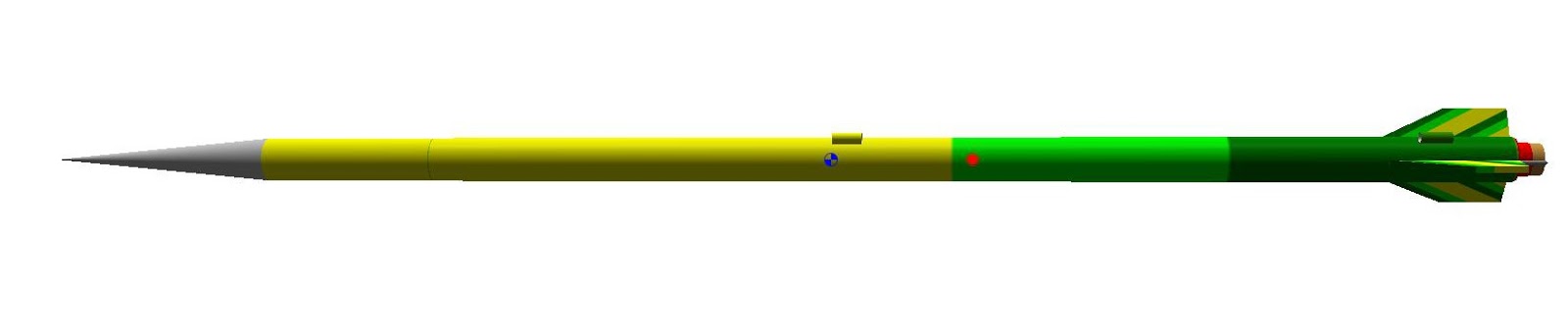
Here I present a proposed paint scheme. This gives you some idea what this beast will look like.
Fast forward about a year while life interrupted, and here I have the rocket finished and I now started the painting. I started with the lightest color (yellow) and painted the payload and upper body tube sections. I also sprayed a bit of the fins where the yellow stripes will be. Next, I masked that off and painted the light green in the middle section of the body tube.
Sorry if this is a bit blurry. While painting the body tube is on a wood dowel that is attached to a larger block of wood. That's my normal rocket holder when I am working on them. After I built it I discovered it wasn't heavy enough to absolutely keep the rocket upright, so you see a bit of the heavy C-clamp that hangs on to the wooden base.

After the lighter green, I masked off the whole top of the rocket and sprayed the remainder of the rocket with a darker green. I learned to use Scotch brand celophane "magic" tape, because I found it seals much better than masking tape and peels off cleaner. I just have to be sure that the edge of the tape is pressed tightly to avoid leaks. I also learned the hard way to always leave a bit of a folded-over end so I have something to find and pull off.

This green paint was from an 10-years or so old paint can, and it came out a bit runny. Getting a good cover ended up taking a lot of coats, and made for a annoyingly heavy finish. Also, the thicker coating left a fairly thick edge that I'm sure will add some extra drag. Looks like I won't be finding that 300' mark with this rocket anytime soon.

Actually it does look nicer than this photo here to the side, for some reason the light green and yellow look the same on here, even though with the natural eye they are clearly two different colors.

I waited a long time between color coats to make sure I didn't have any crazing or other paint formula issues, but the touch-up of dark green only was allowed to dry for a day before I started the decals.
This view shows the "34" that I added. That's because this is rocket build #34 for me. Most of my rockets have the series number on them if the design allows for it. Further up above the dark green, there is a silver ring separating the dark green and light green (which again for some odd reason appears yellow). This ring was from a decal, and not hand painted like I often do.

Here is a much better look at the light green color, which came out in the picture much better. As you would expect, the "EXPERIMENTAL" is a decal, which is accurate since this is an original design that has never flown.

Here is another back end view. The opening here is 13mm, so it will take the smaller 1/2A and A size motors.
In case you haven't realized yet, I am trying to keep you in suspense before revealing the entire rocket, giving you just one little peak at a time.
So let's move on up to the opening for the parachute. Here we see the small "Quest-like" shock cord, which I prefer over the plain rubber type. I'm using my new idea in shock cord mounts again, a small piece of Kevlar with the ends frayed and generously glued against the body tube. Hasn't failed me yet, and makes the replacement of the rubber much easier. Not too much easier though, because I purposely made sure the Kevlar loop was not long enough to reach the end of the (CA-soaked) body tube, to prevent any chance of zipper damage (not very likely with such a small rocket).


The other end of the shock cord is attached to another Kevlar loop, this one sticking through a hole in a small plywood disk, where it is also generously glued and knotted. The Kevlar is lighter than a steel screw-eye, and less likely to break free. The top side of the plywood disk has a body tube coupler glued on. This acts as a bulkhead, and holds the payload tube on the other side.
This is what we see on the other side of the bulkhead. A small bit of plastic foam padding is glued in, and presses against the Altimeter One that is in the payload section. The bits of masking tape on the coupler helps to keep the tube parts tight so we don't have separation in flight.

Ok, we are almost there. On the top side of the payload, above the altimeter, we have another piece of plastic foam, when the whole rocket is assembled, the foam is slightly compressed and keeps the altimeter positioned in the tube and prevents it from rattling around in there. As mentioned earlier, the nose cone is made from carved balsa and the fitting is a tube coupler. The nose cone is painted silver here (silver being my favorite color for a nose cone).

 One more thing I want to show. The bulkhead will work best if there are equal parts on the payload tube and the lower tube. When connected together, the bulkhead/coupler is hidden and so I never know for sure if it is centered well. If one side is too short that can spell failure of the flight or loss of the expensive altimeter.
I usually make a black ring on balsa bulkheads with a sharpie to see that I am attaching the body tubes in the right place. More recently, I just leave the bulkhead exposed a tiny bit when spray painting, and I get a small ring with no effort whatsoever.
In this picture I separated the two body tubes a bit so you can see where the white primer coat left a small white ring on the coupler, so when assembling the two tubes, I can see that I am roughly in the center.

Now I am using a small punch, and every hole is clean and identical. I'm pretty sure that can lead to more accurate altimeter readings, and 100% sure that it looks better.
You may recognize the small burnt Fliz kits guy - or is that excelsior? - on the payload decals. I figured that would be in the spirit of an experimental rocket like this.
Ladies and gentlemen, I would now like to present to you the finished Arroe, rocket #34 from my workshop...(trumpet fanfare)

So there it is. I will add this to the launch schedule, and we'll see if it can actually fly upwards. Looks pretty large up there, but remember it's only a 13 mm motor. I will measure and measure again and give you all the specs, but for now, just admire her beauty!
SPECIFICATIONS
Series Number: 34
Number of Stages: 1
Stock Length: 25.65"
Diameter: 0.736"
Fin Span: 1.6"
Number of Fins: 3
Stock Empty Weight: 30.8 grams
Empty Weight with Altimeter Payload: 37.7 grams
Liftoff Weight Range: 43.7 - 45.6 grams
Motor Diameter: 13 mm
Motor Length: 45 mm
Motor Retention Method: Clip
Payload Interior Length: 3.8"
Payload Interior Diameter: 0.71"
Payload Volume: 1.5 cubic inches
Altimeter Capable: Yes
Recovery Method: Parachute, 9"
Typical Descent Speed: 11mph (estimated)
Recovery Protection Method: Wadding
Shock Cord Mounting: Kevlar
Fin Material: Balsa
Launch Lug Size: 1/8"
Glue Used: Titebond III
Paint Used: Painter's Touch, Testors
Kit Brand: none, original design
Completed: July 12, 2015
FLIGHT LOGS
No comments:
Post a Comment